ARCHITECTURE DESCRIPTION (MODULES)
FINIST is an advanced modern training simulator. Its architecture reflects the demands of today's power engineering business. From the ground up, FINIST was designed to use the latest industry standards established by International Electrotechnical Commission (IEC). This orientation on standards streamlines both its internal architecture and interoperation with external programs. FINIST stores the power system model in Common Information Model (CIM, IEC 61970-3xx). The inter-component communication is carried out using Generic Interface Definition (GID, IEC 6194-40X) group of standards.
FINIST is implemented in C# using .Net framework. It is engineered to take full advantage of modern multi-core multi-processor architectures to provide scalability and adequate real-time performance. The implementation is aggressively parallelized and multi-threaded.
FINIST architecture outline is shown below. The simulator's software components are divided into server- and client-side modules.
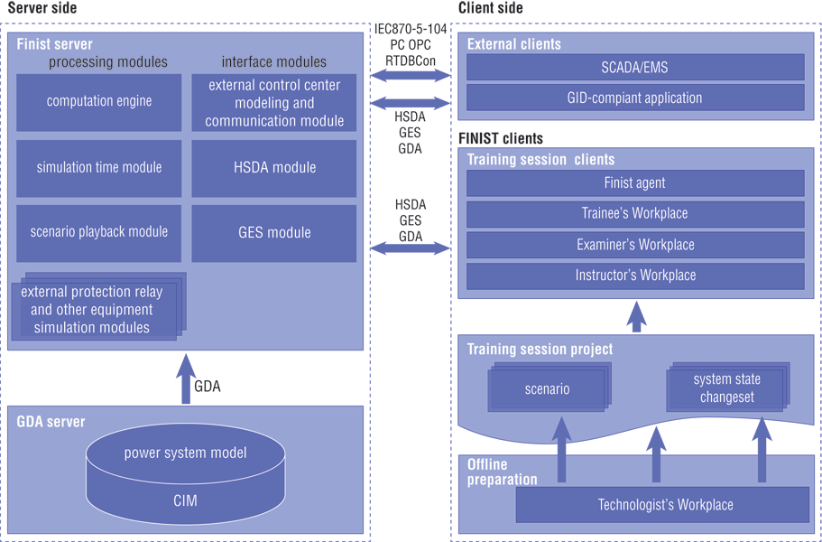
SERVER-SIDE MODULES
The server-side components are FINIST-server and GDA-server. Generic Data Access (GDA, IEC 6197-403) server stores the description of the electric power system in CIM format. The access to the model specification is provided over the GDA protocol.
The FINIST-server is composed of several modules. According to their function, these modules are classified into processing and interface modules. The processing modules carry out most of the computation required for modeling the power system behavior. These modules are:
Computation Engine
It carries out the core computations of the simulated system and coordinates other modules. The Computation Engine calculates the system state, powerflow as well as short and long-term system dynamics.
Simulation Time Module
For the convenience of the training session, the simulation time differs from real-time. The Simulation Time Module may speed up, slow down or suspend the simulation time as required.
SCENARIO PLAYBACK MODULE
This module loads the external events of a particular scenario and executes them at the appropriate simulated time moment.
STANDALONE EQUIPMENT SIMULATION MODULES
Although the computation engine carries out most of the model calculations, for the purposes of modularity and parallelization, the operation of some equipment, such as protection relays and automatic generation control system (AGC), is implemented as separate modules.
The interface modules provide communication with the client modules and external systems. These modules are:
HSDA module
Implements High-Speed Data Access (HDSA, IEC 61970-404) communication protocol. This protocol is used to supply telemetry data to FINIST clients and external programs.
GES module
Implements Generic Events and Subscription (GES, IEC 61970-405) protocol that allows FINIST Clients and External Programs to supply the external events, such as operator actions, to the servers. Similarly, GES is used to notify the clients of alarms in the modeled system.
External Control Center Modeling and Communication Module
This module communicates with the SCADA/EMS system used by the operators. Similar to FINIST client modules, this communication can be carried out using HSDA and GIS. However, FINIST can translate the data streams into other SCADA/EMS and telecommunication protocols. Specifically, to IPC, OPC, RTDBCON and IEC 870.5.104. To simulate real system behavior, this module can introduce delays or errors in the supplied data stream.
For joint multiple control center training sessions, FINIST may communicate with multiple SCADA/EMS and generate separate data streams for each one.
CLIENT-SIDE MODULES
The client-side modules are grouped into Workplaces according to user roles. The Workplaces are classified as configuration clients and training session clients. Users interact with the training session clients during the actual training. These clients are:
Instructor's Workplace
This module uses the training session package to instantiate the system, launch training scenarios, control the execution of individual scenario steps and manipulate simulation time. This module also provides access to the session log whose events can be grouped or filtered as required.
Examiner's Workplace
This module automates the process of evaluating the training session, allows quantifying trainee's performance and makes its evaluation more objective. The module allows the examiner to assign bonuses or penalties to specific trainee actions. The examiner may add comments during the training session, monitor pre-defined system parameters on an oscillogram, receive alarms on operating limits violations.
Trainee's Workplace
This Workplace is to be used by the operator instead of a SCADA/EMS system. It allows the operator to directly issue remote control commands, such as opening a breaker, shedding load, changing generation, relay set-points or transformer tap positions.
Agent
This module is used to initialize the power system model, establish communication with the SCADA, launch and manage server-side modules.
The configuration clients help prepare and manipulate training session package to be used during training.
Technologist Workplace
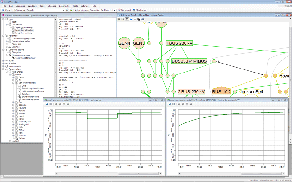
This module is used to configure and debug the parameters of the training session: the initial state and scenarios. Initial state configuration. The state may be designed «from scratch» or imported from a FINIST snapshot or from a SCADA telemetry log. The state then can be further manually tuned to suit the particular training session requirements. If the power system is large, seeing its state at a glance or navigating through all the equipment may be challenging. Technologist's Workplace may connect to the Operator's Workplace graphics system, display the system state, record the Technologists actions (such as closing a breaker or changing transformer taps) and then incorporate the changes into the initial state. Technologist's Workplace also provides a powerful set of table and graphics navigation tools. The system is presented as a set of tables linked by hyperlinks for ease of navigation. Thus, proceeding from a balancing area to the power plant then to a generator and then to the properties of a particular generator becomes is straightforward. The information can be presented as an automatically generated power system graph. This tool proves invaluable in case the graphics forms of Operator's Workplace are not available or are incorrect.
The user can configure individual equipment units as well as system-wide simulation parameters such as maximum power flow calculation mismatch, integration step length, etc.
Scenario editing
This part of Operator's Workplace deals with training scenario design. Each step in a scenario contains a trigger and an action to be executed. This trigger can be arbitrarily complex and can contain an arbitrary combination of Boolean and algebraic functions. The triggers may use constants as well as the modeled power system parameter values. The actions of a step can be simple or nested. Mutually exclusive triggers can generate diverging story lines inside a single scenario. Scenario Editor has the capability of eventually merging these diverging story lines into a single one. The scenarios can be generated out of the logs of previous training sessions.
Librarian
Technologist's Workplace provides convenient means of cataloging of the training sessions, their initial cases and scenarios for future reuse and modification.